ഡിജിറ്റല് ക്യാമറ റിമോട്ട് കണ്ട്രോള്
ഡിജിറ്റല് ക്യാമറ റിമോട്ട് കണ്ട്രോള്


നമ്മുടെ കയ്യിലുള്ള ഡിജിറ്റല് ക്യാമറയെ അല്പ്പം അകലെ മാറി നിന്നുകൊണ്ട് നിയന്ത്രിച്ച് ഫോട്ടോ എടുക്കേണ്ട ആവശ്യം വന്നിട്ടുണ്ടോ ?.ക്യാമറയില് ഉള്ള സെല്ഫ് ടൈമര് അല്ലാതെ വേറെ ഓപ്ഷനുകള് ഒന്നും ലഭ്യമായിട്ടില്ല അല്ലേ.ഇതാ അതിനൊരു ലളിതമായ പരിഹാരം .(വിലയേറിയ പ്രൊഫഷണല് ക്യാമറകളില് റിമോട്ട് കണ്ട്രോള് ലഭ്യമാണ് .ഇവിടെ വിവരിക്കുന്നത് സാധാരണ ഉപയോഗിക്കുന്ന പോയിന്റ് ആന്ഡ് ഷൂട്ട് ഡിജിറ്റല് ക്യാമറകളെ സംബന്ധിക്കുന്ന വിവരങ്ങളാണ്)അല്പ്പം ടെക്നിക്കല് സ്കില്ലും കൂടാതെ ക്യാമറ അഴിക്കുവാന് പ്രോപ്പെര് ടൂള്സ് കൈവശമുള്ളവരും മാത്രം ഈ പണികള്ക്ക് പോകാവൂ .ഇലക്ട്രോണിക്സ് കേരളത്തിന്റെ മിക്ക വായനക്കാരും ഇവയുള്ളവരായതിനാല് അവര്ക്ക് ധൈര്യപൂര്വ്വം മുന്നോട്ട് പോകാം
പക്ഷി നിരീക്ഷണം ,മൃഗങ്ങളെ അവയുടെ സ്വാഭാവിക രീതിയില് അവ അറിയാതെ ഫോട്ടോ എടുക്കല് തടങ്ങി നിരവധി ഉപയോഗങ്ങള് ഇത്തരം റിമോട്ട് കണ്ട്രോള് ഉപയോഗിച്ച് ചെയ്യാം.ഗുണമേന്മയുള്ള വയര് ഉപയോഗിക്കുകയാണെങ്കില് ഇരുപത്തഞ്ചുമീറ്റര് വരെ നീളത്തില് സ്വിച്ച് ഖടിപ്പിക്കാം
പക്ഷി നിരീക്ഷണം ,മൃഗങ്ങളെ അവയുടെ സ്വാഭാവിക രീതിയില് അവ അറിയാതെ ഫോട്ടോ എടുക്കല് തടങ്ങി നിരവധി ഉപയോഗങ്ങള് ഇത്തരം റിമോട്ട് കണ്ട്രോള് ഉപയോഗിച്ച് ചെയ്യാം.ഗുണമേന്മയുള്ള വയര് ഉപയോഗിക്കുകയാണെങ്കില് ഇരുപത്തഞ്ചുമീറ്റര് വരെ നീളത്തില് സ്വിച്ച് ഖടിപ്പിക്കാം
A wired remote control can be very useful for wildlife shooting where the camera is mounted on a tripod 25m away from a hide, It allows you to bring the camera close to the subject without scaring them and to take picture remotely.
Some high-range priced digital cameras have the interface port for remote shutter release; some others may have infrared remote control. The infrared wireless remote control is not very useful, as the infrared sensor is on the front of the camera, thus making it difficult to use while physically standing behind the camera.
Most point and shoot digital cameras do not have remote control interface. Mine is a very cheap one and no need to say. That is why this project.
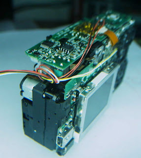
Most controls on a digital camera are only momentary switches. To make them remotely controllable, all we need to do is to open the camera, identify the switches and solder wires to the switches’ terminals. The wires are then routed outside the camera and terminated at a connector. The rest are extension cable and hand switches. The main point is to find a spot on a camera for the connector so that it is reasonably durable for normal use. Most P&S digital cameras are pretty compact and don’t have much room for a multi-pin connector. My case is not an exception but I managed to overcome the problem. Below is the “how-to”.
Disclaimer
This project requires experience of opening and re-assembling YOUR camera and good soldering skill on tiny parts. It also requires appropriate protections against ESD and the high voltage that remains in the flash circuitry. Even though you have the said experience and skills and took appropriate protections, the risk of damaging your camera is high and the author specifically disclaims any and all liabilities for any of your damages arising from following this tutorial. The information provided here is for sharing the experience only.
1. Unscrew and remove the camera enclosure. Identify the switches. I need to make 4 switches remotely controllable. They are auto-focusing, shutter, zoom-in and zoom-out. Find the convenient solder points where the wires will not interfere with normal operation of the original switches.
2. Solder the wires. The switches share a common return (for my camera. Please check yours) such that only 5 wires need to be soldered. I used 30AWG wire wrap wire. (ടെലിഫോണ് കേബിളിന്റെ ഉള്ളിലുള്ള വയര് )Thicker wires may interfere with the operation of the switches or make trouble during re-assembling.
3. Find a spot that the wires can be routed out of the camera. You need to drill a small hole on the camera enclosure to let the wires out. Make a loop on the wires as strain relief.
4. Terminate the wires with a single-in-line connector.
5. Make a cover for protecting the wires during normal use. The surgery is completed. Now you can document the pins-out and test it by shorting the corresponding pins at the connector. Also, operate the camera and make sure that it is functional and the switches are not interfered.
Numerous people have built their own remote controls, but all the designs that I have seen use two separate momentary switches to control the auto-focus and shutter action.
I modified a wheel mouse so that the left and right button become zoom-out and zoom-in; and pressing the wheel down will do focusing; turn the wheel will do shutter action. It sounds great, right? Do I need electronic circuitry to do it? Not at all. Just remove the unused parts and make room for one more micro switch. It is pretty simple to do the mod and all 4 controls are at your finger tips. See below for the "how-to".
1. Open the mouse, cut copper traces so that the 3 micro switches (left, right and the one under the wheel shaft) are isolated.
2. Remove the ball and the parts to make room for one more micro switch. Install the micro switch and attach a wire to the wheel as shown below. The wire here is not for electrical connection but for mechanically pushing the switch when the wheel is turned back.
3. identify the normally-open contacts and solder the wire accordingly. I used 10m network cable which has 4 pairs of wires, more than what I needed.
4. Test the operation of switch.


Comments
Post a Comment