Outdoor Garden Solar Lights
Outdoor Garden Solar Lights
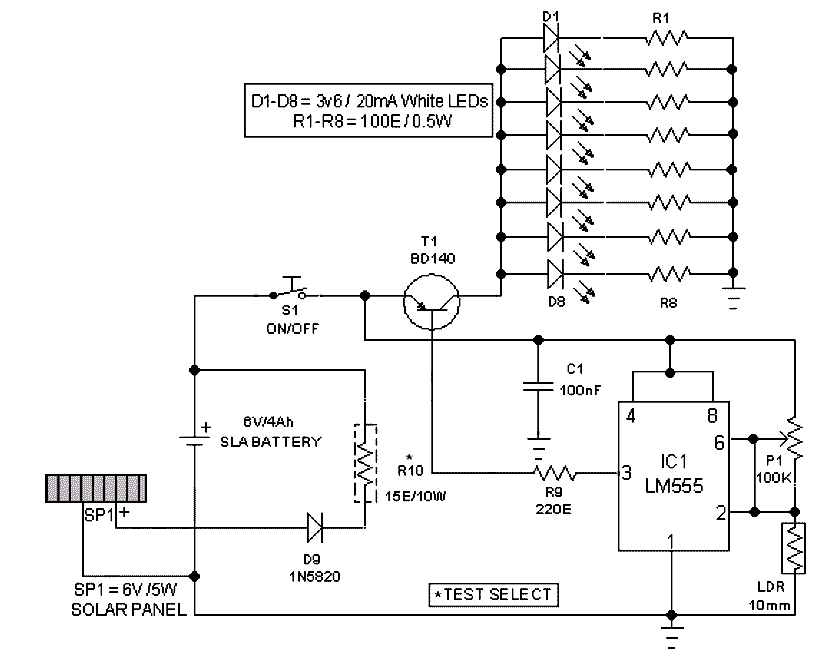
T.K. HareendranThis Outdoor LED Solar Garden Lights project is a hobby circuit of an automatic garden light using a LDR and 6V/5W solar panel. During day time, the internal rechargeable 6 Volt SLA battery receives charging current from the connected solar panel through polarity protection diode D9 and current limiting resistor R10. If ambient light is normal, transistor T1 is reverse biased by IC1 (LM555).
Here IC1 is wired as a medium current inverting line driver, switched by an encapsulated light detector (10mm LDR). Multi-turn trimpot P1 sets the detection sensitivity. When ambient light dims, transistor T1 turns on to drive the white LED string (D1-D8). Now this lamp load at the output of T1 energizes. Resistors R1-R8 limits the operating current of the LEDs. When the ambient light level restores, circuit returns to its idle state and light(s) switched off by the circuit.
Assemble the Outdoor Solar Lights circuit on a general purpose PCB and enclose the whole assembly in a transparent plastic box. Drill suitable holes on the top of the enclosure to mount the mini solar panel (SP1) and the light sensor (LDR), and in front for fitting power switch (S1) and the sensitivity controller (P1).
Fix the battery inside the cabinet using a double-sided glue tape/pad. Finally, the LDR should not be mounted to receive direct sunlight. It must be mounted at the top of the enclosure, pointing to the sky say southwards. This circuit is very simple. So interested and experienced hobbyists can alter/modify the whole circuit as per their own ideas without any difficulty (Just try a 6V relay with T1 to drive more number of LED strings)
Outdoor LED Solar Lights Circuit Schematic

Sometime few educational blogs become very helpful while getting relevant and new information related to your targeted area. As I found this blog and appreciate the information delivered to my database.
ReplyDeletestainelss steel solar path lights outdoor